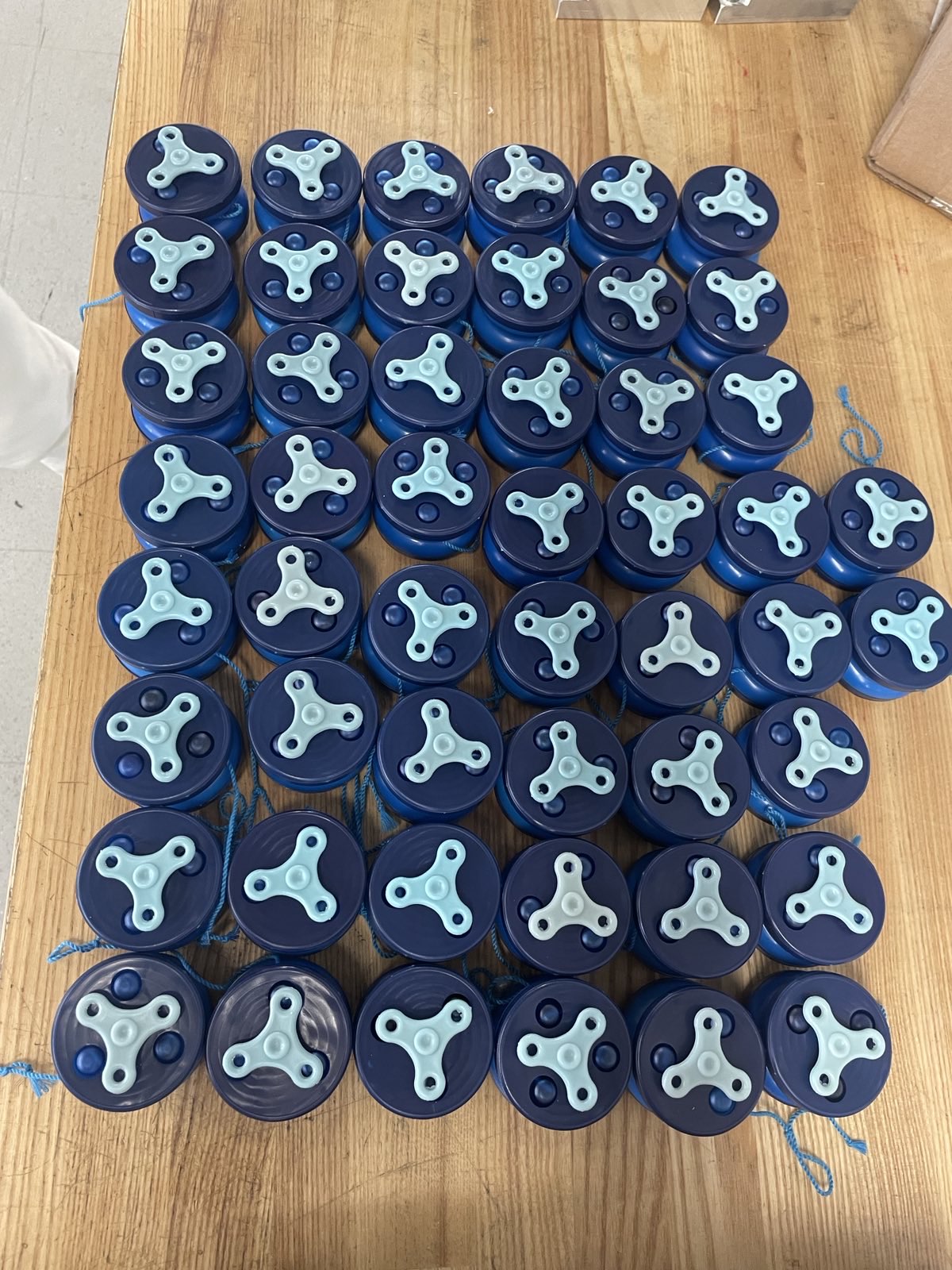
Jekyll2025-12-01T01:43:12+00:00https://jonathan-anziani.github.io/feed.xmlJonathan Anziani’s PortfolioJonathan Anziani's mechanical engineering design and fire spinning performance portfolioJonathan AnzianiBulk Manufactured Yo-Yos2025-07-03T00:00:00+00:002025-07-03T00:00:00+00:00https://jonathan-anziani.github.io/uncategorized/bulk-manufactured-yoyos50 yo-yos designed and manufactured for Manufacturing and Design II. Each half of the yo-yo consists of an injection molded ring and base press fit together, with a bearing and fidget spinner attathed to the ring. I designed the fidget spinner and with that I had to design the press-fit diameters between the ring, bearing, and fidget spinner.
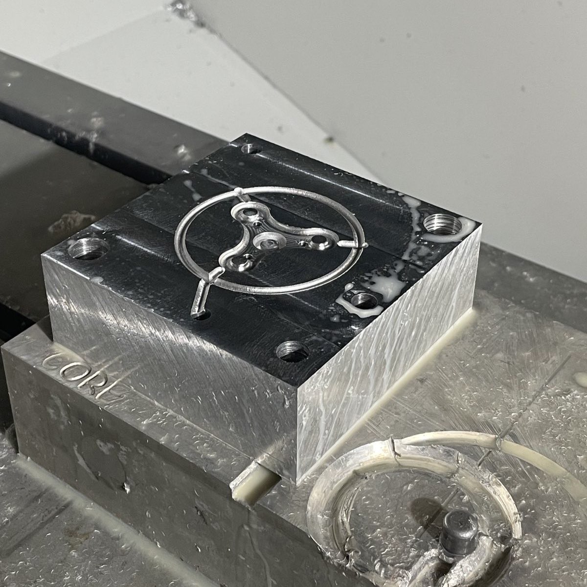
I was responsible for the CAD, CAM, and CNC milling of some of the molds, which were designed to take into account shrinkage of the injected plastic.
None of the press fits failed after a 4 foot drop test of all 50 yoyos as a result of our design tolerances.
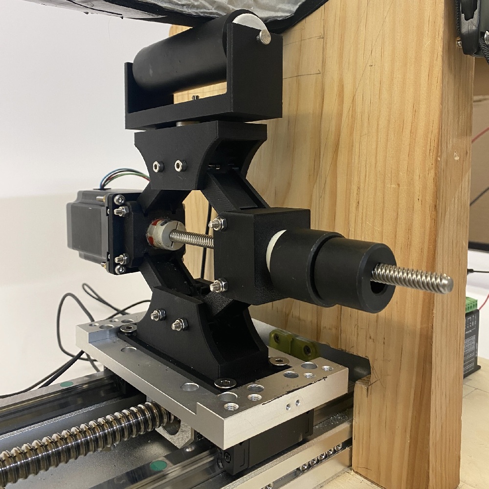
]]>Jonathan AnzianiForce-Controlled Massage Therapy2025-07-03T00:00:00+00:002025-07-03T00:00:00+00:00https://jonathan-anziani.github.io/uncategorized/force-controlled-massage-therapyFor MIT’s Medical Device Design class, I worked in a team of seven to design a force-controlled automated massaging device that measures muscle stiffness in real-time.
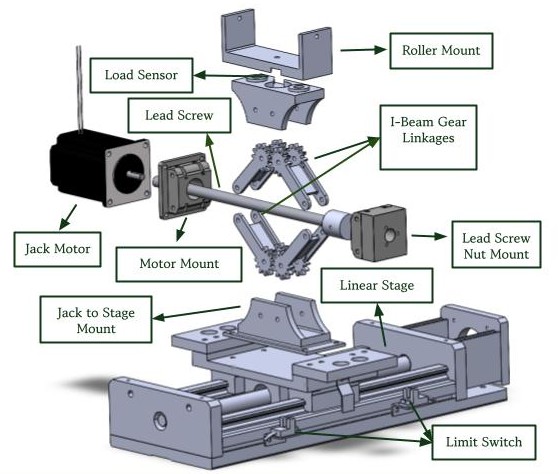
The device consists of three key components: a scissor lift-inspired mechanism that applies force onto the limb, a load cell that measures the force applied, and a linear stage that moves the stage along the limb. By measuring the force on the limb and knowing the distance pressed into the muscle, real-time muscle stiffness can be measured. Future iterations of this project will implement closed-loop stiffness feedback control, replicating how a clinician can feel muscle stiffness during a massage.
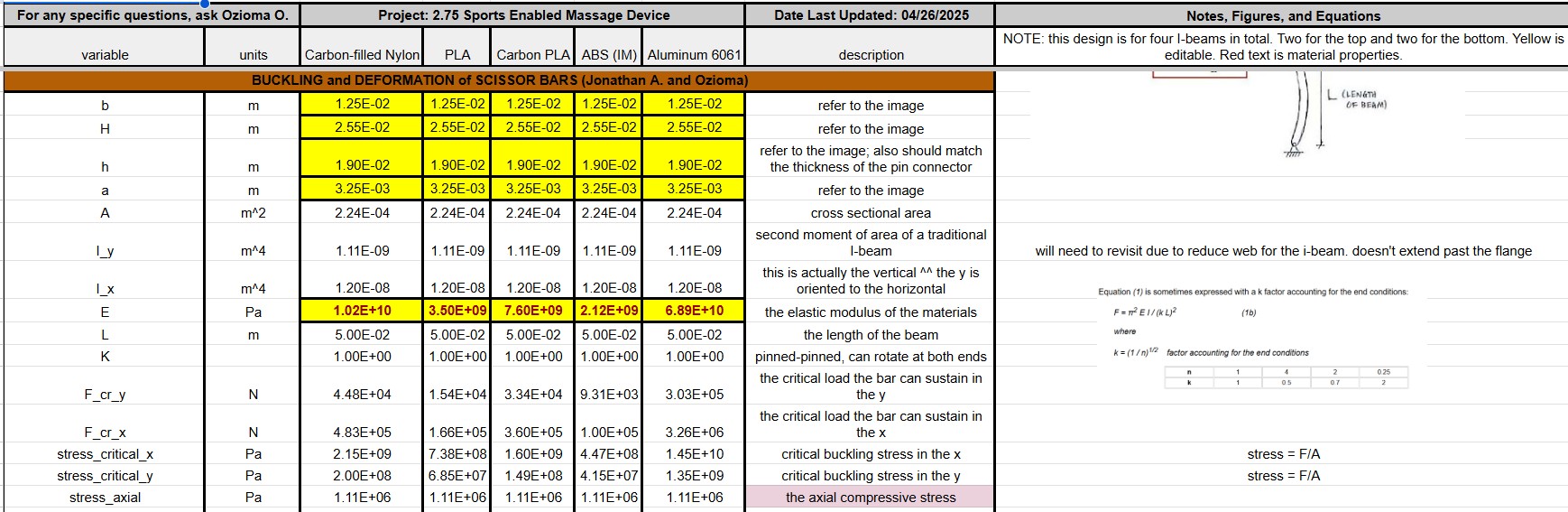
I was primarily responsible for the load analysis of the 3D-printed structure and the power transmission design. For the load analysis, I modeled the yeilding and buckling failure criterion using a spreadsheet to easily tabulate and communicate the calculations to teammates and project mentors. For the power transmission, I calculated the stepper motor torque and speed requirements needed to replicate the motion and force measured from a massage clinician. With these specifications, I chose sufficient stepper motors for the linear stage and scissor lift and desgned a mounting part to integrate the motors into the rest of the system while preventing a structural collapse when reaching holding torque. A sample of these calculations are shown below.
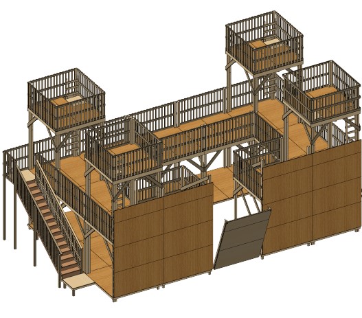
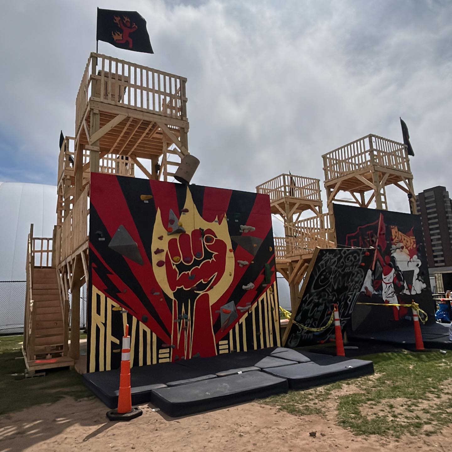
]]>Jonathan AnzianiThree-Story Tall Castle2025-07-03T00:00:00+00:002025-07-03T00:00:00+00:00https://jonathan-anziani.github.io/uncategorized/three-story-tall-castleI was apart of a small team of project leads overseeing the design, construction, and disassembly of a three-story tall wooden castle for MIT’s freshman orientation. The structure is 44’x24’x24’ in size with three-story tall towers, two-person fixed angle rock climbing walls, and one-person angle adjustable climbing wall.
During the design phase, I used beam bending calculations, Finite Element Analysis, and existing structural engineering code to ensure the structure can handle loads from people standing, loads from people climbing, and loads from wind. Wind loads were caluated by researching referencing Massachusettes regulations, and all calculations were validated by MIT Environmental Health and Safety as well as a contracted structural engineer before construction.
During construction, I would train and direct over 100 students (primarily incoming students with no prior experience) on the measuring, cutting, and assembly of wood using power tools.
]]>Jonathan Anziani3D-Printed Rocket Toy2025-06-29T00:00:00+00:002025-06-29T00:00:00+00:00https://jonathan-anziani.github.io/uncategorized/3d-printed-rocket-toyThis toy was my first experience with CAD and 3D printing as an assignment for MIT’s Toy Product Design class. It consists of four buttons, a rechargable battery, and speakers powered by an Arduino Uno where the user has to press the buttons in order of them lighting up.
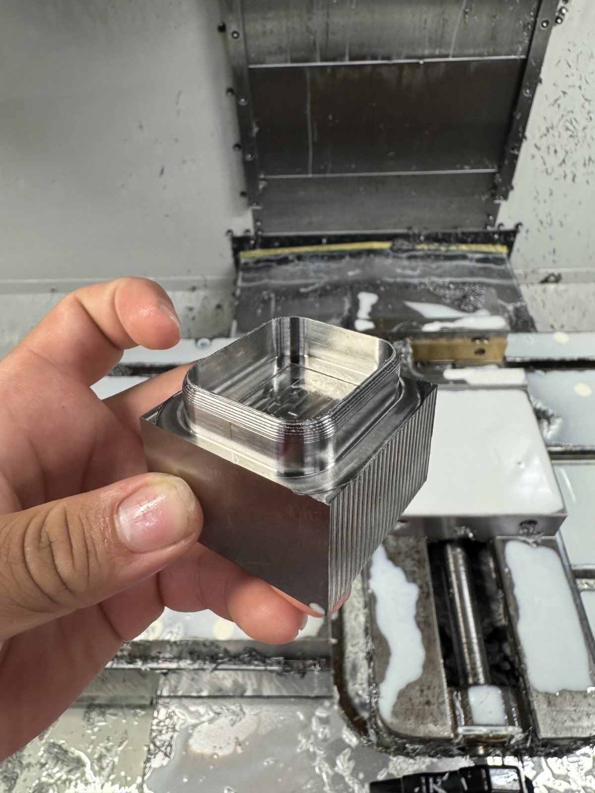
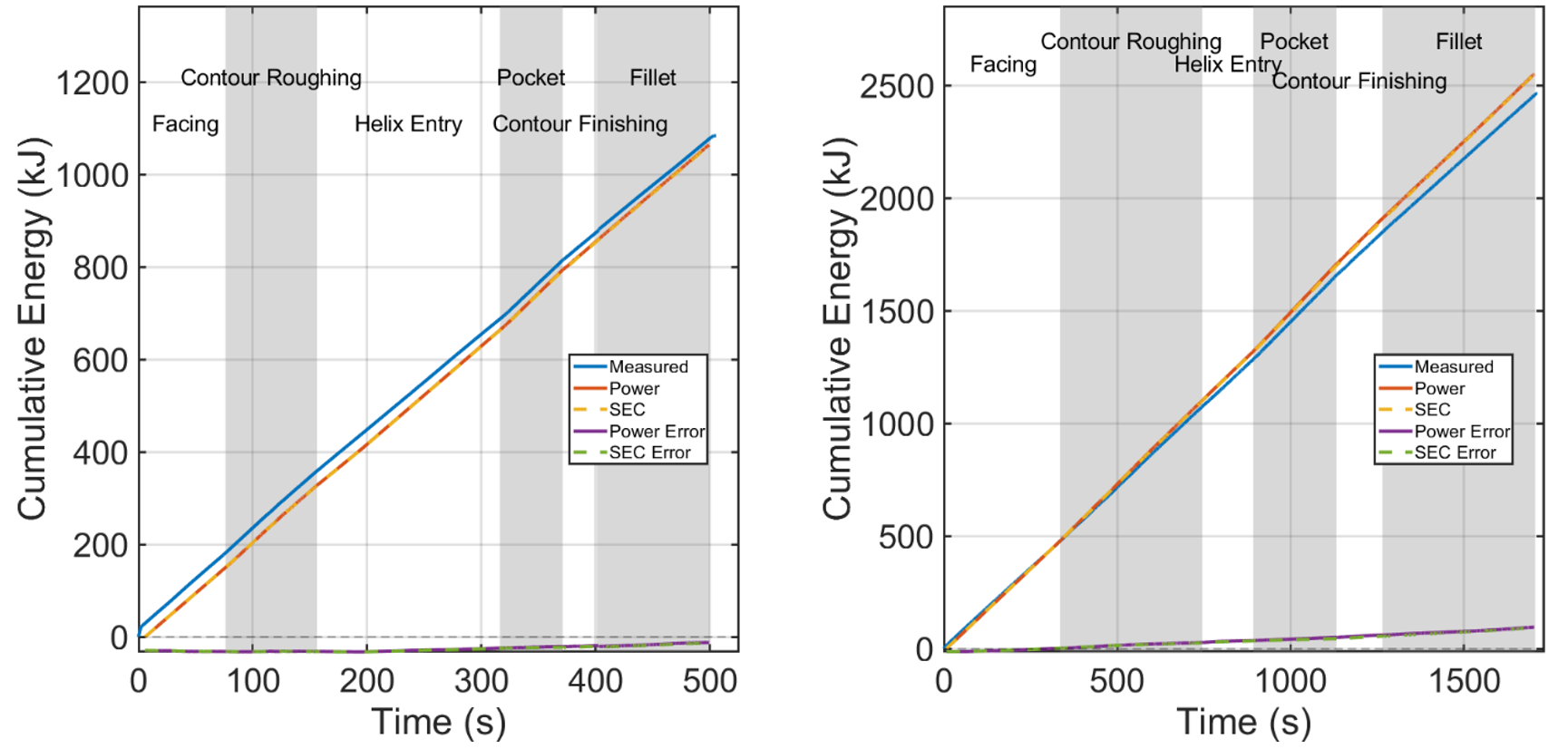
]]>Jonathan AnzianiG-Code Based Toolpath Simulation for Predicting CNC Energy Consumption2025-06-29T00:00:00+00:002025-06-29T00:00:00+00:00https://jonathan-anziani.github.io/uncategorized/modeling-cnc-energy-consumptionFor my undergraduate thesis, I developed a G-code based program in MATLAB that simulates the material removal process and predicts the energy and power consumption required to CNC machine a part. The simulation was validated by comparing the simulated energy to that of a part in both aluminum and titanium, showing an energy prediction error of 2.11% and 3.48% respectively.
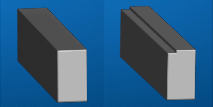
Machined validation part in titanium
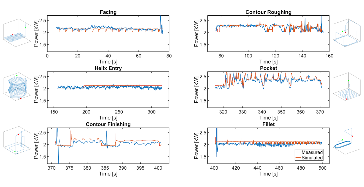
Empirical and predicted power vs time for machining the validation part in aluminum separated by different operations in the toolpath
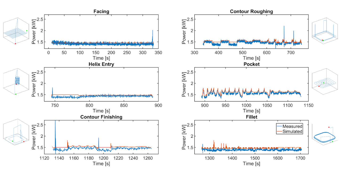
Empirical and predicted power vs time for machining the validation part in titanium separated by different operations in the toolpath
Empirical and predicted energy vs time for aluminum (left) and titanium (right)
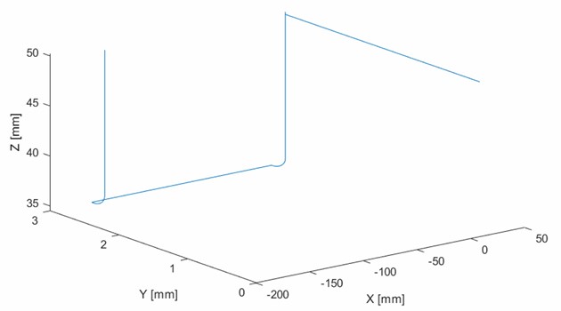
This program functions by first reconstructing the toolpath from the G-code.
The simulation then runs a virtual endmill along the toolpath in a voxel mesh of the workpiece, replicating material removal.
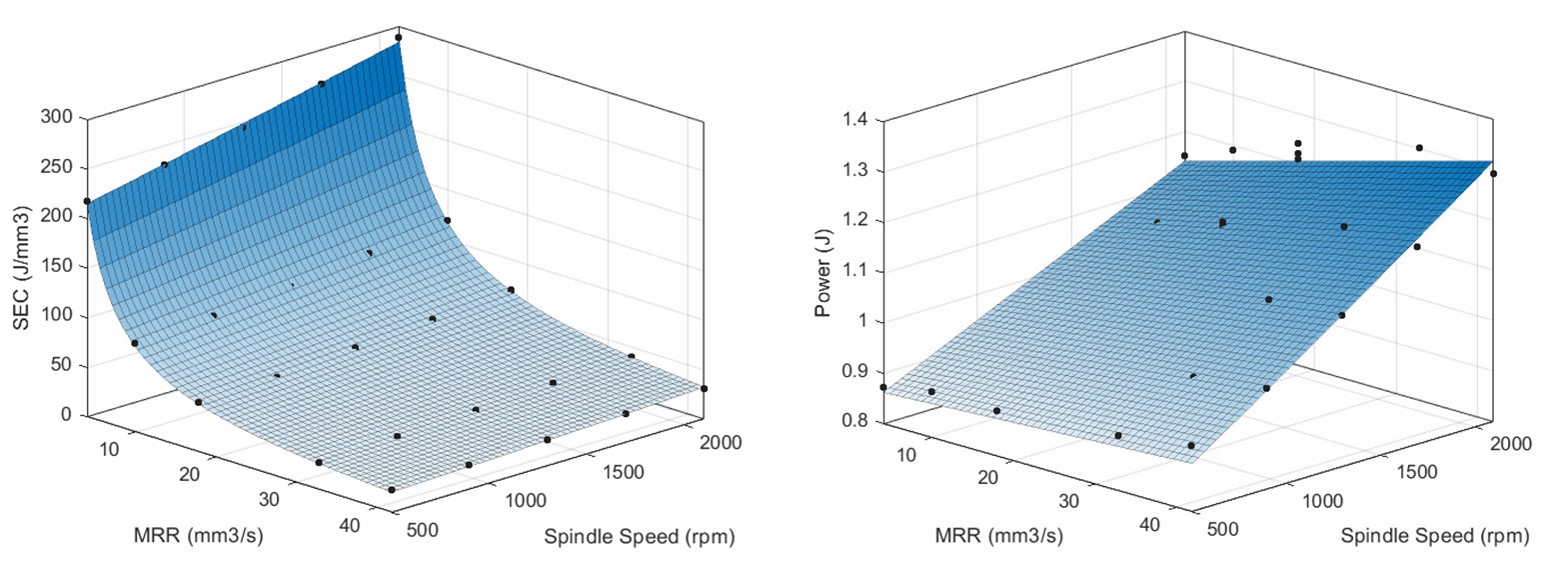
The model predicts the power and specific energy consumption for a timestep by relating it to the simulated material removal rate and spindle speed using existing analytical models and machine-dependant power data. An example relation is shown below.
The full thesis with comparisons and sensitivity analyses can be found here.
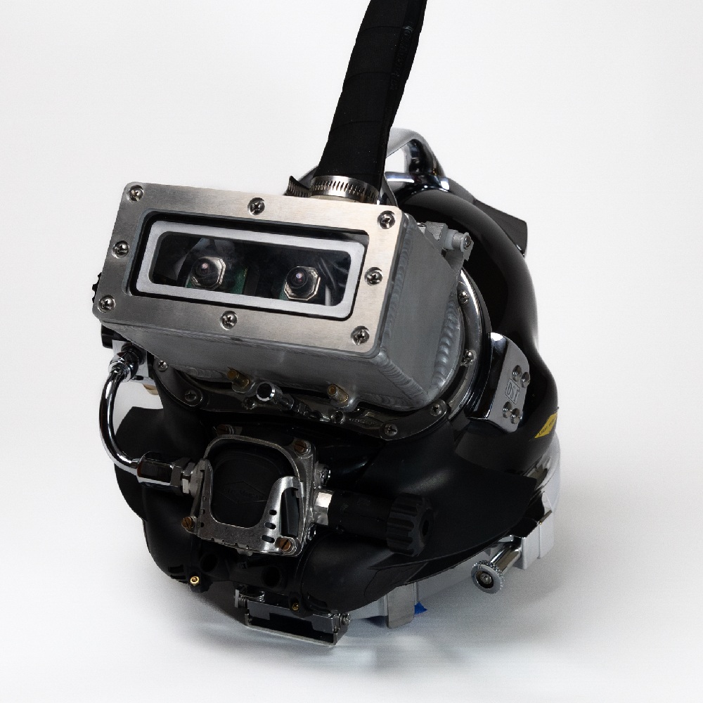
]]>Jonathan AnzianiUnderwater Vision Augmentation (MARLIN)2025-06-29T00:00:00+00:002018-03-20T20:00:52+00:00https://jonathan-anziani.github.io/uncategorized/underwater-vision-augmentationThis underwater vision assistance device was designed in a team of twelve to allow commercial divers see underwater in low-light, high-particulate situations.
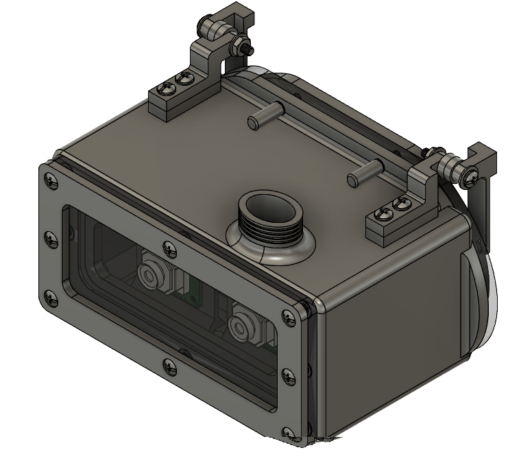
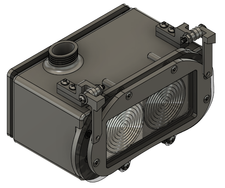
Two cameras, a screen, and a pair of lenses are housed in a waterproof aluminum case designed to mount onto the industry standard Kirby-Morgan diving helmet.
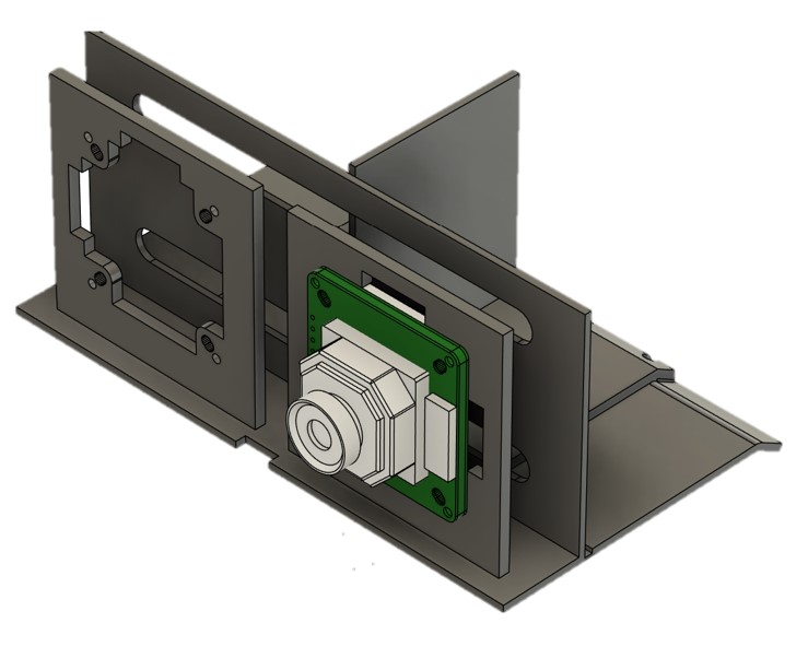
I mostly focused on the mechanical design and fabrication of the prototype. For the final prototype, I designed a 3D-printed component mounting bracket that minimizes overall product size while still being removable and replacable. I also helped design the faceplate to would fit snugly with the faceshield of the Kirby-Morgan helmet, improving visual clarity by reducing the water gap. Additionally, I assisted the electrical sub-team by testing and choosing the final cameras used in the prototype based on hardware compatability.
More details including a user testimony from underwater testing at the Woods Hole Oceanographic Institution can be found in the product prototype presentation here.